

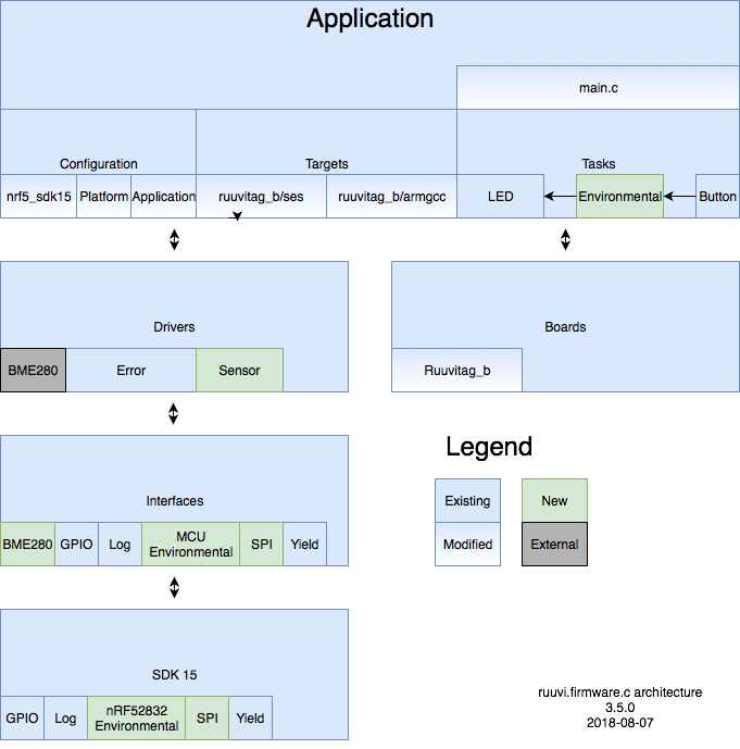
In this part of the tutorial we’ll develop a sensor interface which can use any backend to read sensor data and implement the backend with nRF52 built-in temperature sensor. Then we’ll write SPI drivers to read external sensors and implement the sensor backend with Bosch BME280. Final code can be found at Ruuvi GitHub in the ruuviblog-branch, tag 3.5.0-alpha. Please follow part 1 of the series for details on how to clone the repository and compile the code. Final hex of this tutorial can be downloaded from the Ruuvi Jenkins.
Sensor Interface
Generally any sensor we’ll use will have some common parameters, such as resolution, sample rate, scale, Digital Signal Processing (DSP) function and parameter for the DSP. Additionally we might be interested in starting the sensor, stopping the sensor or taking a single-shot measurement.
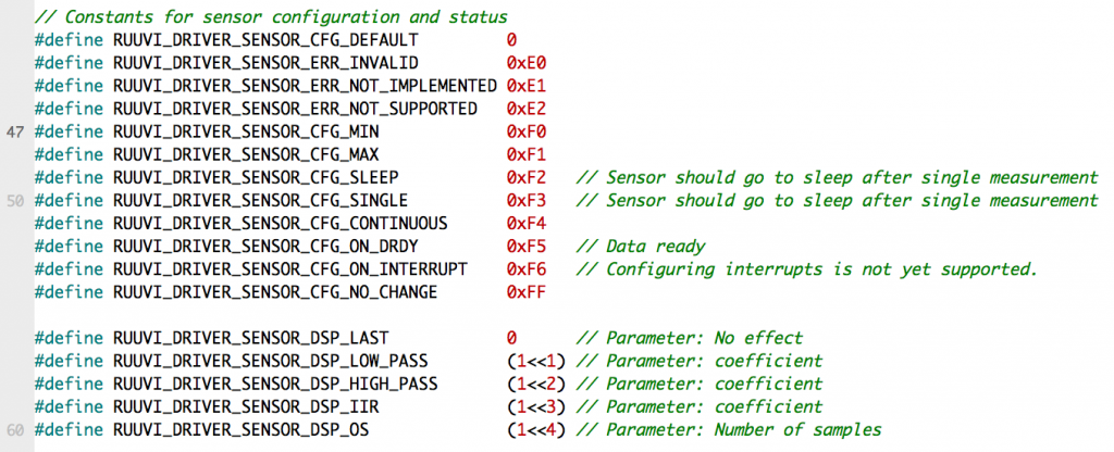
We’ll also want to define a few fixed meanings for our sensors, such as RESOLUTION_MAX or SCALE_MIN. This allows us to setup a variety of sensors without knowing the exact capablities of the underlying device. We’ll also use 0 as a reasonable default value. This allows us to memset configuration to all zeros and end up with a reasonable values without having to explicitly set any parameters we don’t really care about.
Because eventually we want to send the configuration over BLE we’ll conserve space in our interface. We’ll use uint8_t values to configure the sensors. DSP functions are bit flags to allow combining several options.
As we want to use any sensor available we’ll define a common interface to the underlying sensor using function pointers. This allows us to use same code with nRF52 temperature sensor and BME280 environmental sensor to get environmental data, nRF52 will just return “invalid” values on pressure and humidity. It could be argued that C++ would be better choice for interfaces, however we’ll not mix the two unless absolutely necessary for some reason.
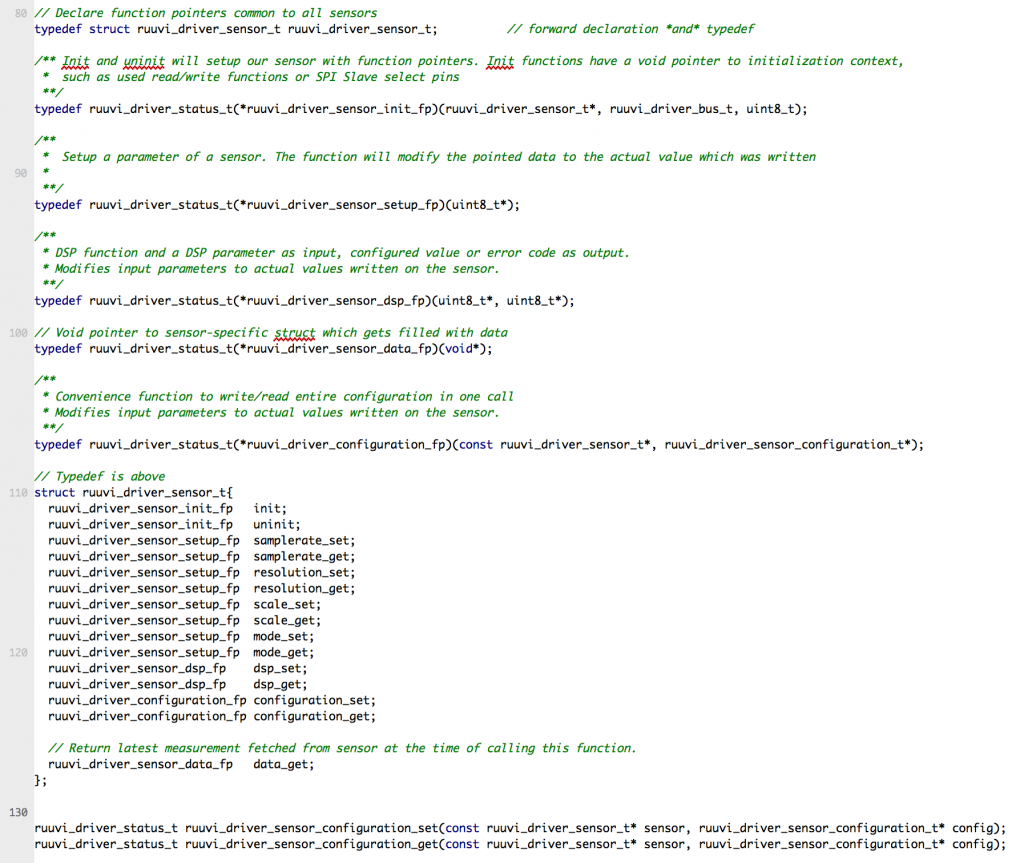
Our initialization allows bus to be defined, this lets us to support selecting if sensor driver should use I2C or SPI with the given sensor. We’ll also pass a uint8_t handle which helps the program to select the correct sensor. On I2C this handle is address of the sensor, on SPI it is the GPIO pin used to select the sensor.
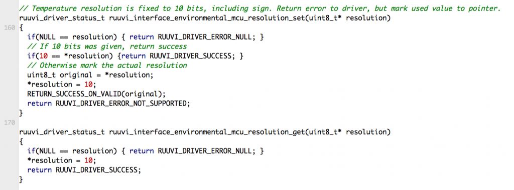
We’ll try to keep our interface simple. Sample rate is in Hz and resolution is in bits. Values 1 … 200 are allowed, 0 having special meaning of default and values over 200 being reserved for constants with a special meaning. If our sensor does not support the exact given value we’ll interpret the value as at least, For example if resolution of 9 bits is requested while 8 and 10 bits are supported we’ll opt for 10 bit resolution.
A more difficult question is what the resolution and scale should represent if they’re not MIN, MAX or DEFAULT. Scale is harder to represent than resolution with uint8_tas the type. It works well for something like accelerometer scale where we can have 2, 4, 8, 16 G without problems. Units such as Pascal are more challenging: we might have something like 100 000 Pa which should be represented by the scale number.
To keep our interface simple we’ll apply the same principle as we did with the sample rate and resolution. Scale is in meaningful physical unit such as G. Same goes for the sample rate: accelerometer could reach 5 kHz in a low-resolution mode, however any out-of-bounds value is represented with MAX. While this does restrict some of corner cases, we’ll just accept that any special use-case will require more work and try to fulfill the general needs.
Digital Signal Processing functions are even more mixed bag, as there might be different desired combinations of functions which require entirely different parameters. To keep in line with keeping things simple, we allow a bit flag of hardware-supported DSP functions and passing single, common parameter to them.
The sensor interface defines function pointer for setting and getting each of the parameter. The interface will modify given values to the value which was written, or to default if the sensor does not support given parameter. Return code is SUCCESS if reasonable action could be taken, or error code such as NOT_SUPPORTED if there is no way to fulfill the requested setting.
Environmental Sensor
Environmental sensor data interface
We’ll use floats in our sensor data format, as this allows us to have enough scale in reasonable SI-unit. We’ll also add timestamp in milliseconds to the data, even if we do not have RTC implemented yet.
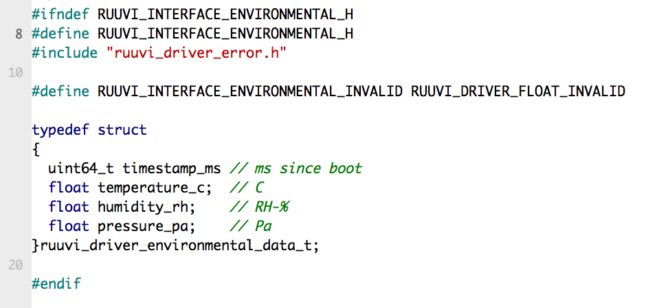
Variables are postfixed with the name of the unit to avoid any ambiquity in what kind of values we’re dealing with in the code.
nRF52 Environmental sensor implementation
Environmental implementation is simple in nRF52, as we don’t have anything but simple, single synchronous data_get -function available in nRF52. Our initialization function setups the nRF52 offset compensation register and function pointers. Bus and handle definitions can be ignored here. Uninitialization NULLs the function pointers, but no other action is necessary.
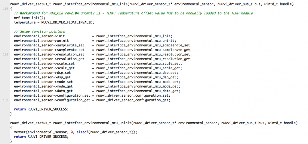
The set functions return RUUVI_DRIVER_ERROR_NOT_SUPPORTED unless user happens to enter the default value of setting, such as resolution of 10 bits. We’ll also allow DEFAULT, MIN, MAX and NO_CHANGE. Getters mark the pointed value as the default and return RUUVI_DRIVER_SUCCESS.
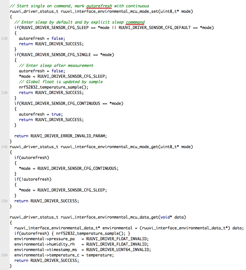
We‘ll mimic the continuous sampling functionality by setting a flag to refresh the data on data_get. This allows programs which rely on continuous mode on environmental sensor to work reasonably with the nRF52 temperature sensor.
BME280 Environmental sensor implementation
BME280 implementation is a lot more complex because we have to interface with an external sensor over the SPI bus. Fortunately Bosch provides platform-independent C-driver for the BME280 and we need to provide just a few basic functions to use it.
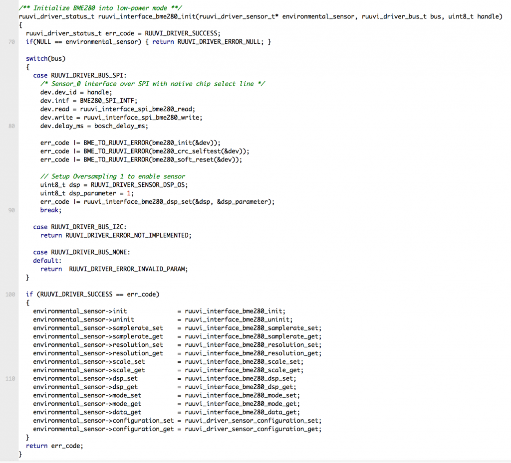
Initialization is similar to nRF52 implementation. We’ll check if the selected bus was SPI, setup the handle and read/write/delay -functions, call the Bosch driver to initialize the BME280, run a self-test and perform a soft reset. Finally we’ll set oversampling to 1 on each sensor to avoid the gotcha of BME280 not sampling unless oversampling is at least 1. If no errors occurred, we setup the function pointers and return SUCCESS.
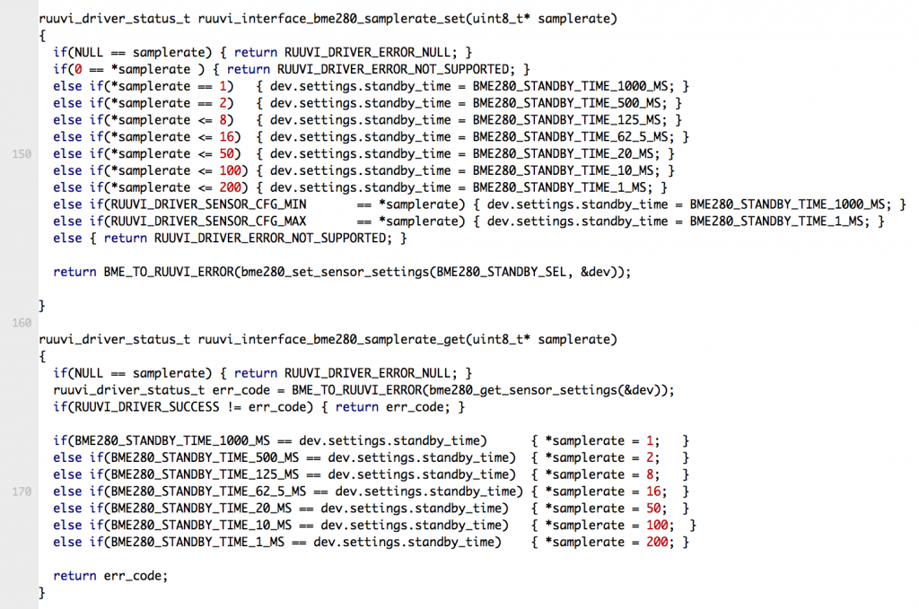
BME280 naturally has a lot more of environmental sensor features than nRF52, however using most of these features is really straightforward switch-cases for selecting appropriate options. Only gotchas we have are that oversampling setting of each sensor element has to be at least 1, there is no fixed sampling rate but rather a delay between samples, and the sampling time is dependent on the oversampling setting. We’ll accept some imprecision in the sampling rate and just assume that we can get the desired rate by selecting the delay which would give us the desired sampling rate.
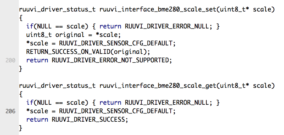
Resolution and scale are hard to define as a single number, since we’re dealing with 3 different units of measurement. Therefore we’ll return the default as the parameter value and return an error if setter had something else than MIN, MAX, DEFAULT or NO_CHANGE.
SPI Drivers
Interface
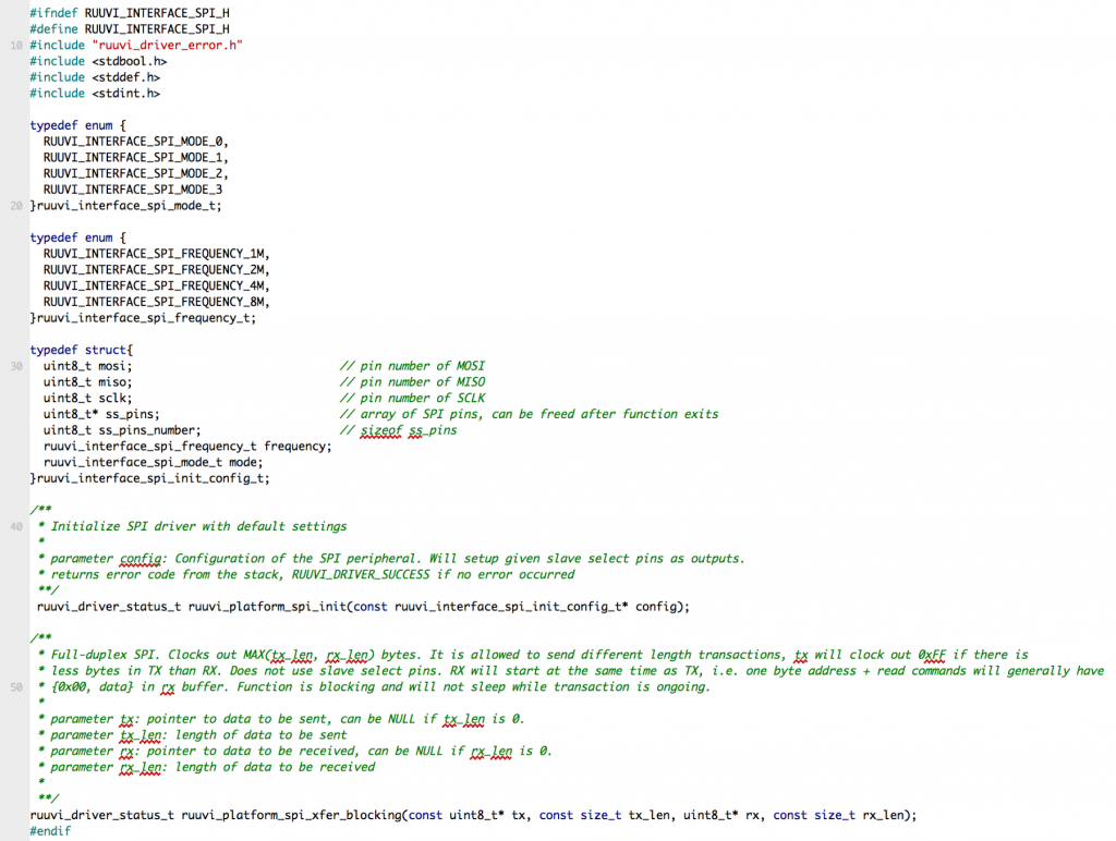
Our interface has 2 functions: Initialization and a blocking full-duplex transfer. Our other drivers for peripherals will implement wrappers which use the transfer function.
The interface defines SPI mode and frequency enumerations as well as initialization structure. This allows us to avoid tying the driver to the board definitions, but it requires the application to match the board settings to the driver.
Implementation
The implementation itself has nothing we’ve not seen before, we check input parameters, pass them on to Nordic SDK and return any error codes. Nordic SDK would support a lot of finesse with Direct Memory Access (DMA) and Peripheral-Peripheral Interconnect (PPI), but we’ll opt for simple blocking transfer functions for now. Maybe we’ll revisit the implementations later on if power profiling reveals that the functional firmware consumes a lot of power during the SPI reads, but for now that would be considered premature optimization.
BME280 wrappers
Bosch BME280 driver expects read, write and delay functions with the given signatures:
int8_t ruuvi_interface_spi_bme280_write(uint8_t dev_id, uint8_t reg_addr, uint8_t *reg_data, uint16_t len);int8_t ruuvi_interface_spi_bme280_read (uint8_t dev_id, uint8_t reg_addr, uint8_t *reg_data, uint16_t len);void bosch_delay_ms(uint32_t time_ms);Delay is simple, we just pass the call to ruuvi_platform_delay_ms and ignore the return value. Read and write require a bit more work: our SPI transfer function is full-duplex with two buffers whereas Bosch function is address + R/W data.
We’ll implement the BME280 SPI functions in the interface, i.e as platform-independent. We’ll call the platform-provided GPIO-control functions and SPI-transfer function in the wrapper.
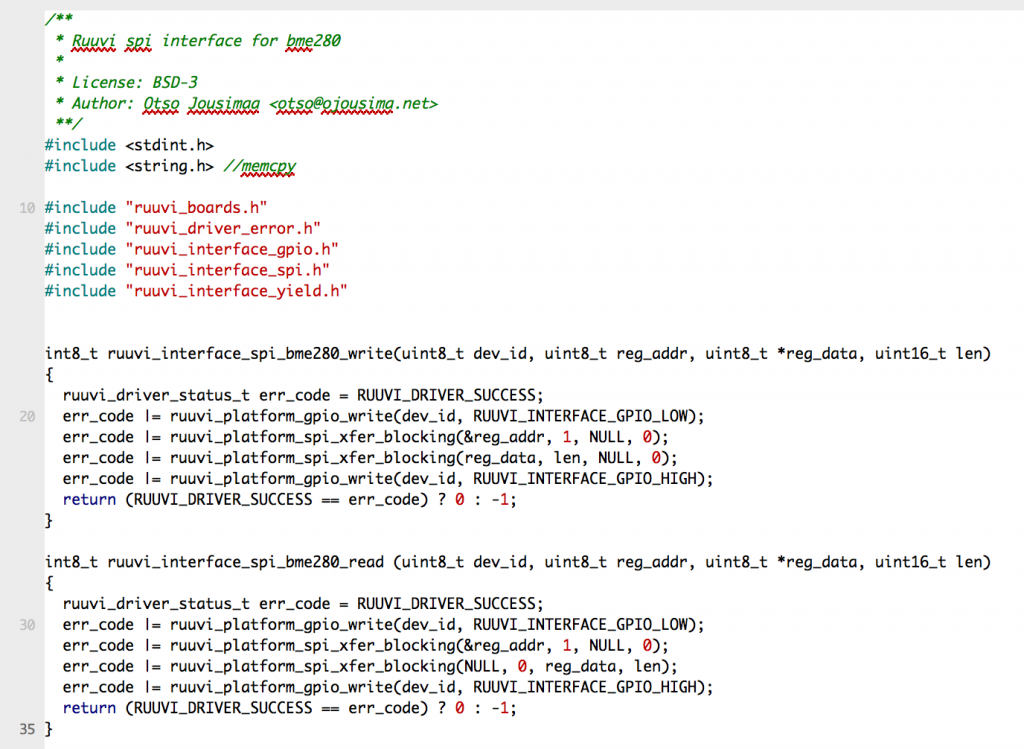
Essentially what we do here is to split one function call from Bosch driver to 4 calls:
- Select the given SPI device by driving the GPIO line low
- Write target register
- Read/write data from register
- Unselect the SPI device by driving the GPIO line high
Initializing SPI drivers
Initializing the SPI takes a bit more work than previous GPIO or log implementations, as our boards might have different pinouts or maximum speeds for the SPI. We’ll create a dedicated task for the SPI which reads the board definitions and passes them on to the driver.
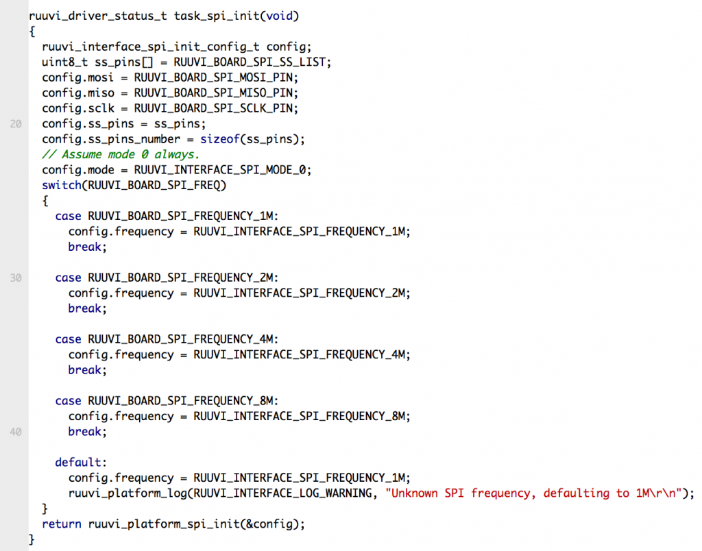
We take a shortcut here and assume that we’re going to use the SPI mode 0. Frequency is dealt with a switch-case statement and pinouts are taken as-is.
Selecting the Environmental Sensor at Boot
Ideally we’d only need to add a single line new_environmental_sensor_present 1 to our board definition and our interface would try to initialize the new sensor if the driver has been implemented. However this would introduce a dependency between drivers and boards and we’re avoiding those dependencies as much as we can. Therefore we’ll need to add the possible sensors in our environmental sensor intialization task. This does mean some extra work for porting the application to a new board with a new environmental sensor, however we’ll just accept it and do the extra work on a new target board if necessary.
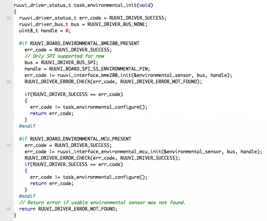
The definitions RUUVI_BOARD_ENVIRONMENTAL_BME280_PRESENT and RUUVI_BOARD_ENVIRONMENTAL_MCU_PRESENT are defined in the board file. If the board might have both sensors, we’ll compile in the code to test them. On BME280 we allow NOT_FOUND -error, because we might be running this code on a RuuviTag B Basic without the sensors. If the BME280 is found, we return and environmental sensor is initialized and configured. If BME280 is not found, we try to initialize nRF52 temperature sensor as our environmental sensor. Our configuration function takes constants from the application_config.h
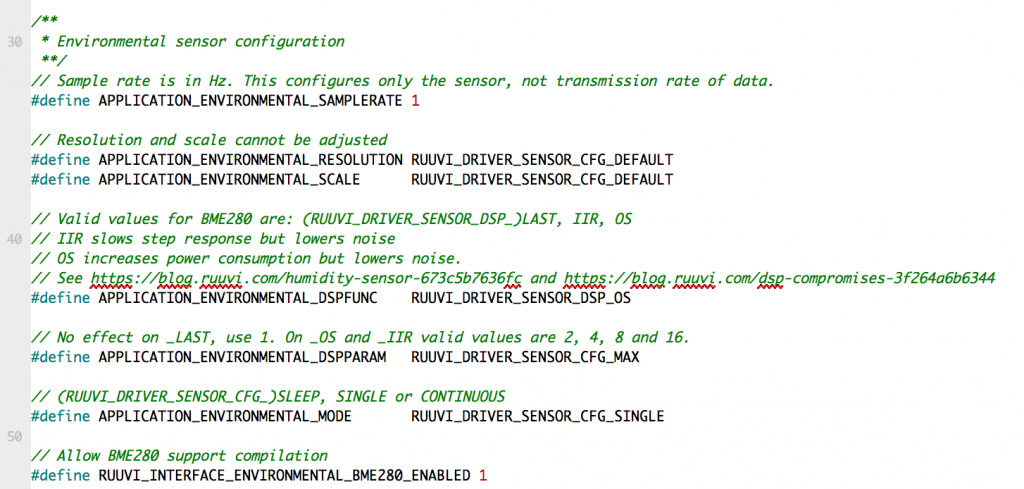
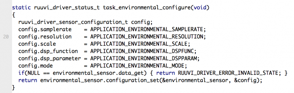
Our configuration defaults to the single-shot mode as we’re going to trigger the environmental measurement on a button press. Because we’re assuming that button presses are going to be relatively rare we’re oversampling as much as the hardware allows to get minimal noise on the measurement.
Using the environmental sensor
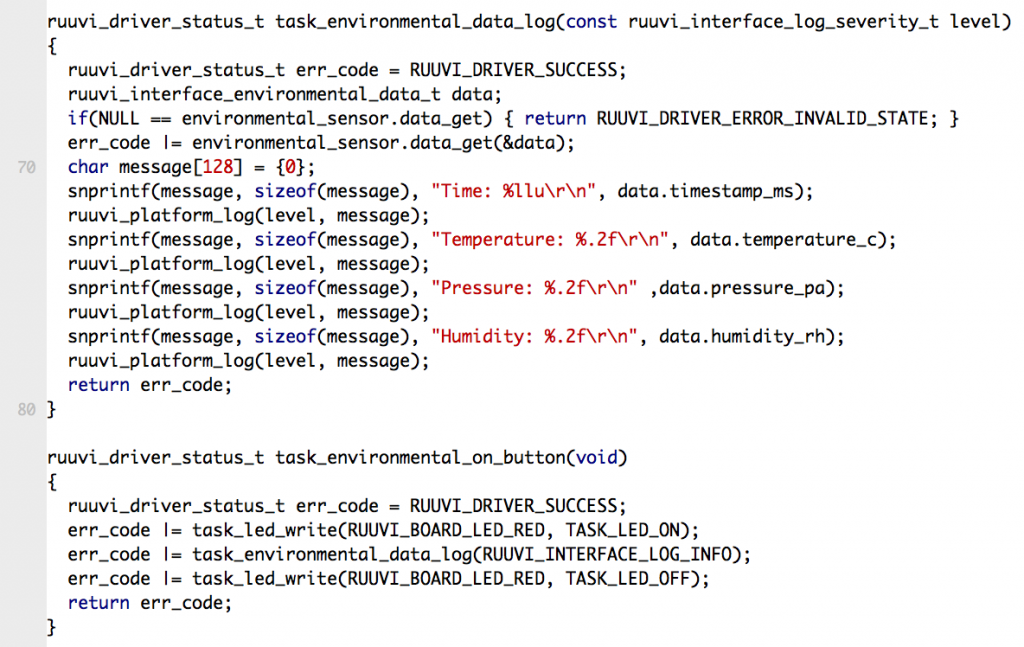
Now we can do something a bit more interesting with our board than just blink LEDs. Let’s create an on_button function which takes an environmental sample, reads the sensor data and prints it out.
One noteworthy point is that printing out the uint64_t and float is pretty expensive in terms of the code size. After enabling the compiler flags our code has grown by 3.3 kB! There is another serious issue with the complier flags: our Jenkins build will have different behavior since the code is compiled with a different makefile and different compiler flags. We’ll fix the Jenkins build in a later tutorial, as this part is long enough already.
We start mimicing the RuuviFW functionality by turning the RED LED on for the duration of activity while we’re at it. Let’s replace the previous task_led_cycle task with task_environmental_on_button
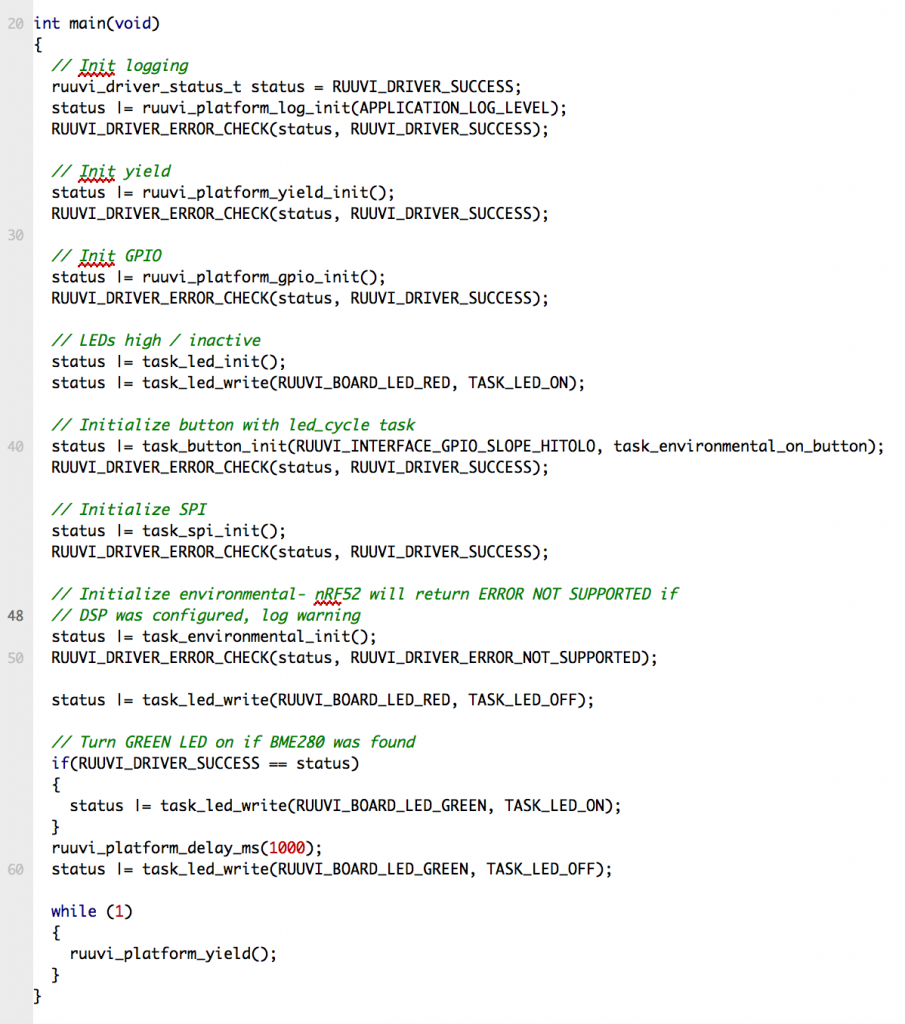
We also implement another of RuuviFW features here: nRF52 will return ERROR_NOT_SUPPORTED when we try to configure the oversampling. Status won’t be RUUVI_DRIVER_SUCCESS at the end of initialization, and we won’t be turning the GREEN LED on. This is pretty hackish at this point, because another configuration in application_config.h would not give out such an error. However, in the next part when accelerometer is added we’ll always have ERROR_NOT_FOUND on basic model and the GREEN LED works as intended.
Testing it out
Functionality
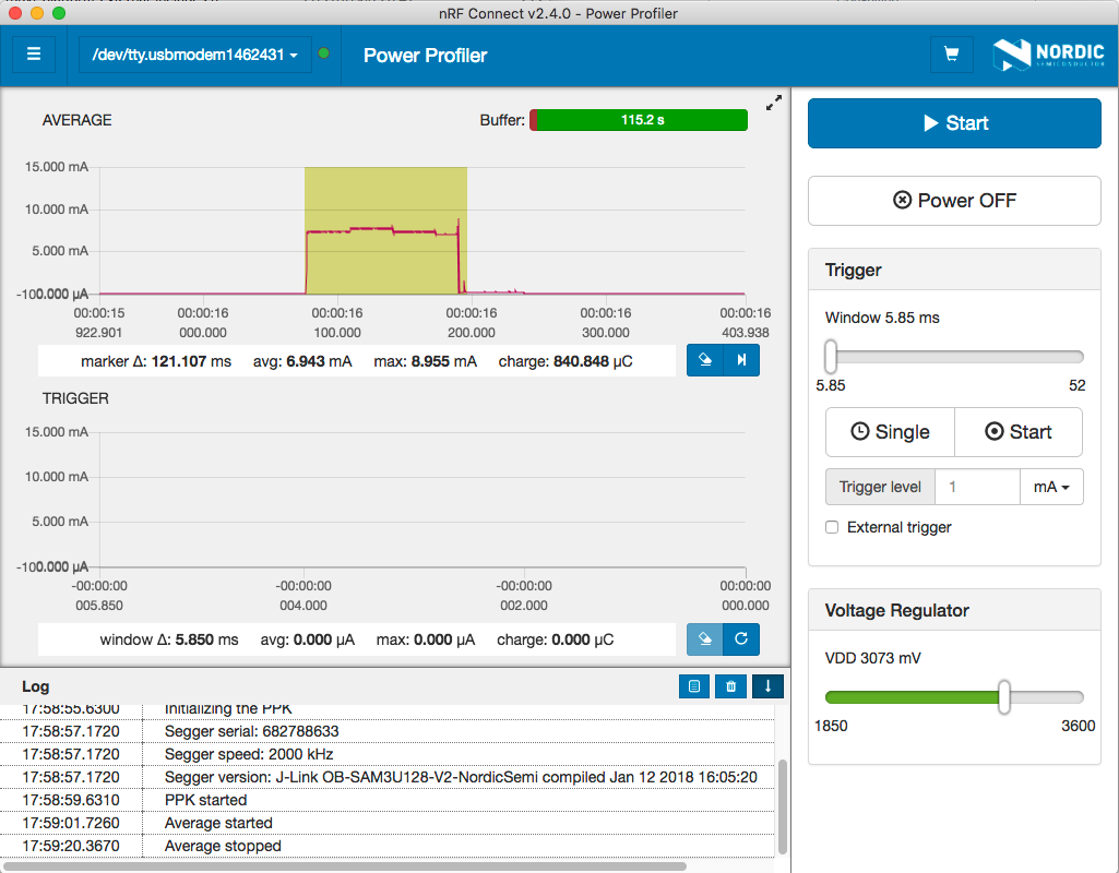
If everything works as intended, we have a program which initializes the sensors and intelligently selects between BME280 and nRF52 depending on what is available. On button press the data is printed out on terminal.
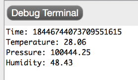
The sensor values look reasonable on model +, timestamp is the UINT64_MAX which is the invalid value because we haven’t implemented the RTC yet. Let’s see how it looks on basic model without the BME280.
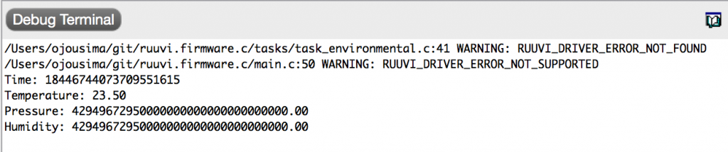
We get warnings on model basic because the nRF52 does not have builtin hardware oversampling. Temperature readings are very different between the devices, one possible explanation is that the nRF52-DK below my model plus heats up the board. Model basic gives out invalid pressure and humidity because the nRF52 does not support measuring those. Our drivers seem to work as intended.
Power consumption
As always, low power consumption is critical for us. If our code “works”, but it chews through the battery in a matter of weeks we have to get back to the drawing board and fix the issues before going further. Let’s see how the consumption looks on RuuviTag+.
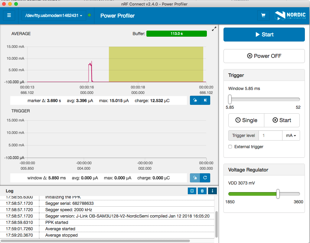
This time our sleep current seems to be 3.4 μA, down from 4.1 μA in the last part of the series. This might be related to the ongoing heatwave in the Europe, last week was quite a bit hotter than now. Or maybe it is just measurement inaccuracy. Anyway, we have nothing to worry about at this time.
Let’s check how it looks on a RuuviTag basic without the sensors.
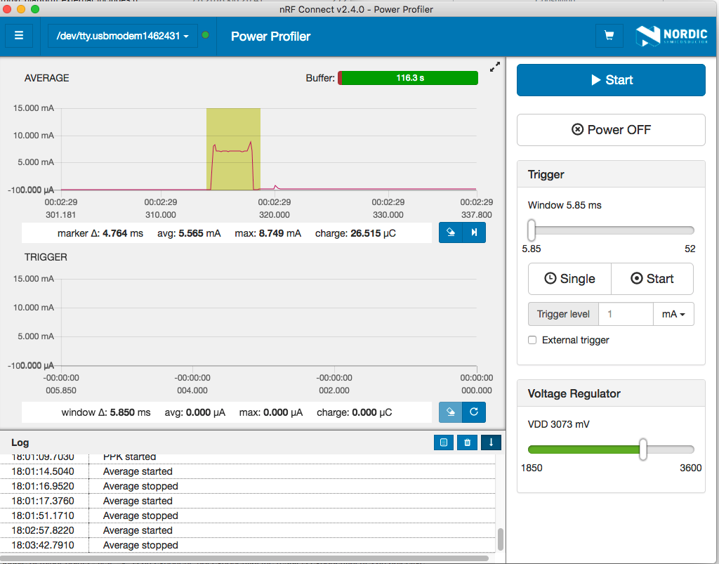
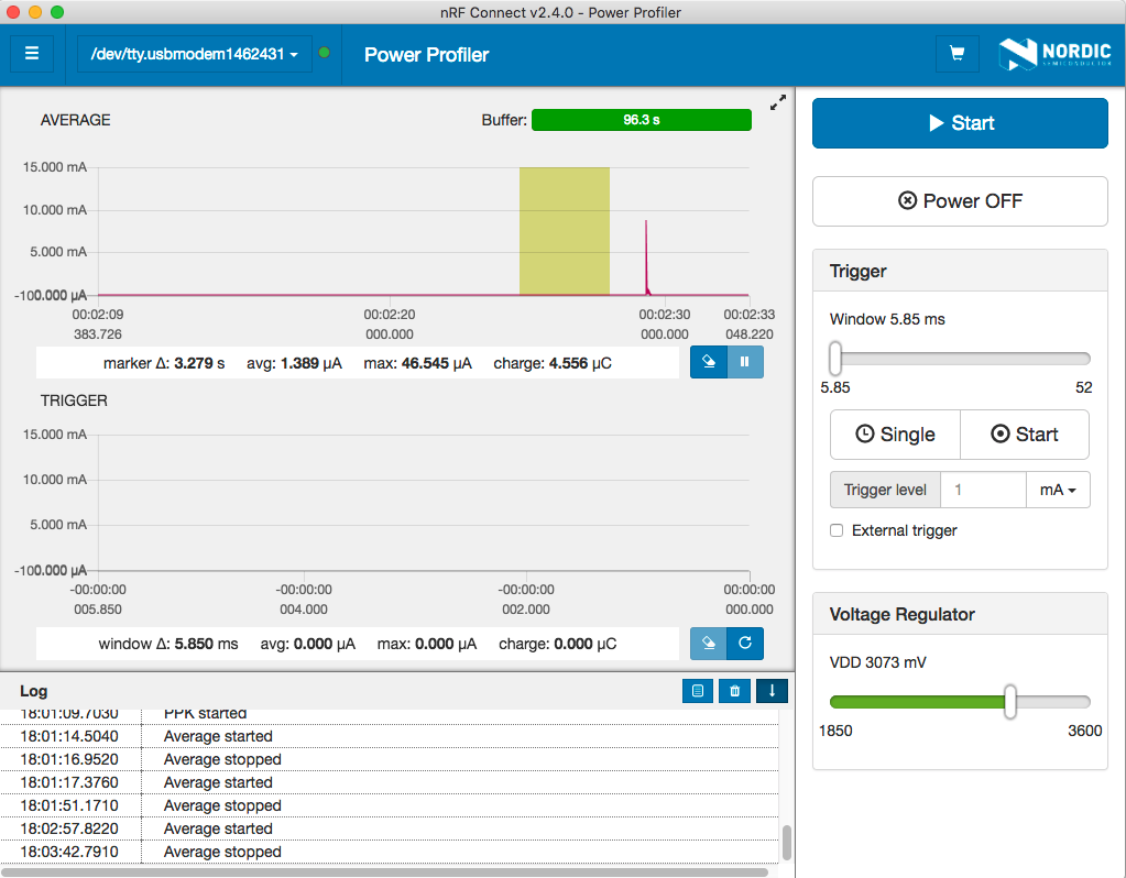
On RuuviTag basic we’re at 1.4 μA as we don’t have the standby current of sensors to worry about. This does not make a practical difference, as both tags consume so little that our battery would expire long before the consumption drains the battery. So far, so good.
In conclusion
This was the longest post so far, and we have advanced a lot. Now we have:
- A generic interface to sensors
- Intelligent selection of the sensor backend for our application
- Generic SPI driver for external sensors and BME280 specific wrappers to it
- Integration to the Bosch BME280 driver
- nRF52 as a backup to BME280
The next few tutorial parts are going to be simpler, as we build on this foundation and add accelerometer, RTC and ADC battery measurements to the firmware.
Stay tuned and follow @ojousima and @ruuvicom on Twitter for #FirmwareFriday posts!